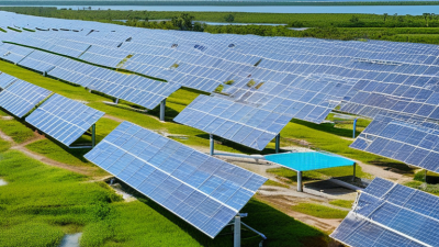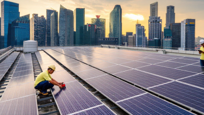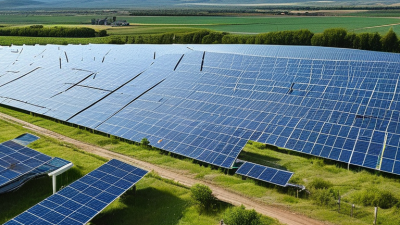
A solar project is more than a field of shining panels. It is an engineered energy system that converts sunlight into electricity, then delivers that power to homes, businesses, or the grid. A typical project solar site includes photovoltaic modules, inverters, mounting structures, cables, transformers, monitoring equipment, and sometimes battery storage. Each panel produces direct current, while the inverter converts it into alternating current for practical use.
The numbers explain its rapid growth. The International Energy Agency’s Renewables 2024 report projects nearly 5,500 gigawatts of new renewable power capacity between 2024 and 2030, with solar photovoltaics providing the largest share. IRENA’s Renewable Power Generation Costs in 2023 report also found that utility-scale solar PV costs fell by about 90% between 2010 and 2023. The global weighted-average levelized cost reached approximately USD 0.044 per kilowatt-hour. Costs vary by land, financing, labor, grid access, and sunlight quality. That detail matters.
A project begins with site screening, solar-resource measurement, environmental review, and grid studies. Engineers then select the panel orientation, system size, and connection design. During operation, sensors track production, temperature, voltage, and equipment performance. A clear afternoon may show thousands of panels working quietly, while clouds can change output within minutes. Storage can reduce that variability, but batteries add cost, maintenance, and material considerations. Solar is powerful. It is not effortless.
This article explains how a solar project moves from planning to construction and long-term operation. It also examines the practical weaknesses that optimistic brochures sometimes overlook, including land constraints, recycling questions, transmission delays, and uncertain financial assumptions.
A solar project is a planned system that converts sunlight into usable electricity. It includes more than photovoltaic panels. The project may contain inverters, mounting structures, cables, monitoring equipment, and batteries. Its size can range from a small rooftop installation to a large ground-mounted power facility. The purpose remains clear: produce electricity safely, reliably, and at a suitable cost.
What defines a solar project is its complete design and operating plan.
Developers assess sunlight, land conditions, roof strength, shading, temperature, and local grid capacity. Engineers then calculate expected output using panel orientation, system losses, and seasonal weather patterns. A realistic plan also covers permits, construction, electrical protection, maintenance, recycling, and eventual equipment removal. Without these details, a panel layout is only an idea.
The grid connection matters greatly. A project may serve one building, several nearby users, or a wider electricity network. Batteries can store daytime generation for evening demand, but they add cost, weight, and maintenance needs. Field inspections often reveal problems that computer models miss, such as muddy access roads or unexpected shadows. Estimates can be wrong. That is why monitoring data, independent reviews, and clear performance records are important throughout the project’s life. A technically impressive system may still fail if it ignores local weather, community concerns, or daily electricity use.
What Is a Solar Project and How Does It Work?
A solar project uses photovoltaic panels to turn sunlight into usable electrical power. Each panel contains solar cells made from semiconductor materials. Light becomes current. When sunlight reaches a cell, its energy disturbs electrons inside the material. This movement creates direct current, commonly called DC electricity. Stronger sunlight usually produces more power, although heat, dust, and shading can reduce output.
The panels send DC electricity to an inverter, which changes it into alternating current for household or commercial equipment. This conversion allows electricity to flow through normal building circuits. A meter can measure production and consumption. Extra electricity may charge batteries or move into the public grid, depending on the system design and local rules. The result depends on more than panel size. Roof direction, seasonal sunlight, cable losses, and equipment condition also matter.
In practical installations, even a narrow shadow from a tree branch can lower production across several cells. Shading matters. Engineers study hourly sunlight patterns before choosing panel angles and electrical layouts. They also check ventilation because overheated panels can lose efficiency. A simple energy estimate may look convincing, but it can ignore cloudy weeks or future tree growth. Numbers can mislead. Reliable planning uses measured site conditions, conservative forecasts, qualified installation practices, and regular inspections. Even then, solar output changes from hour to hour, so storage or grid support may still be necessary.
A typical solar photovoltaic system receives about 1,000 watts of sunlight per square meter under standard test conditions. With a module efficiency of approximately 20%, around 200 watts per square meter becomes direct-current electricity. Inverter conversion and other system losses reduce the usable alternating-current output to roughly 180 watts per square meter.
What Are the Main Components of a Solar Project?
A solar project is a coordinated system, not simply a field of panels. The solar modules capture sunlight and convert it into direct-current electricity. Mounting structures hold each module at a designed angle, while foundations resist wind, rain, and seasonal movement. Small details matter here. Poor alignment can reduce output.
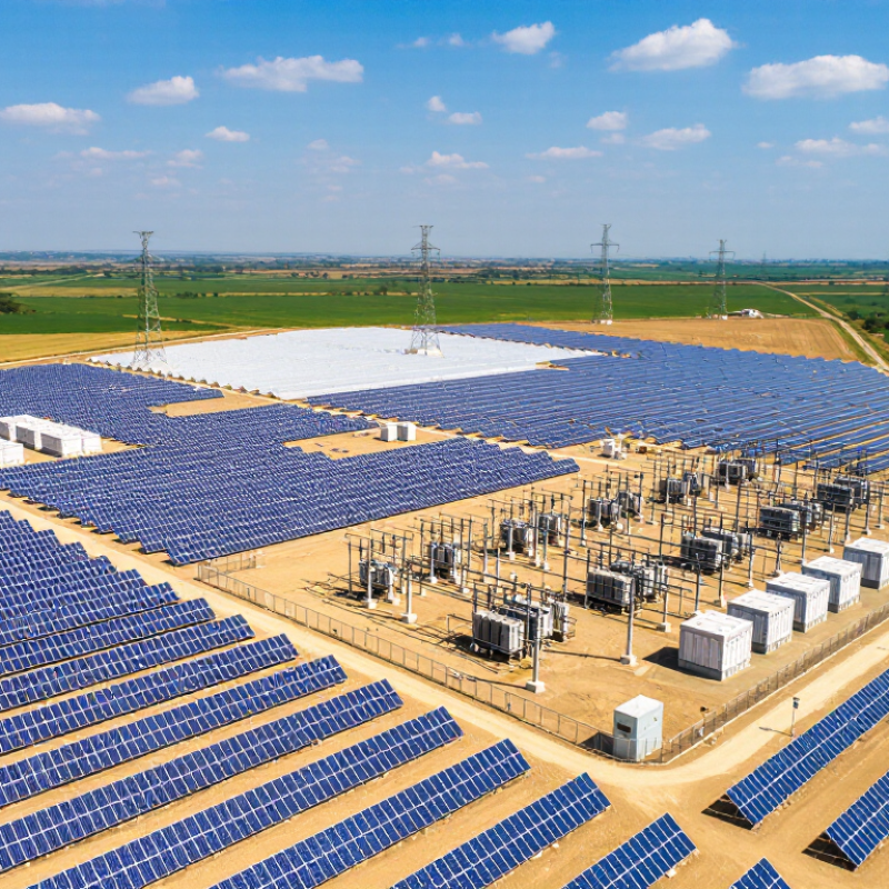
Inverters convert direct current into grid-compatible alternating current. Combiner boxes collect electricity from several module strings and provide basic protection. Transformers then raise the voltage for transmission. Monitoring equipment records energy production, temperature, alarms, and equipment performance. Operators use these readings to identify a damaged cable or an underperforming section before losses become large.
Some projects add battery storage, especially where evening demand is high. A storage system includes battery racks, a battery-management system, thermal controls, and a bidirectional inverter. The final connection includes switchgear, protection devices, metering, and grid-approval equipment. According to IRENA’s Renewable Capacity Statistics 2024, global solar capacity reached about 1,419 GW by the end of 2023. That scale makes reliable balance-of-system design increasingly important.
Real projects are less tidy than diagrams. Dust, shading, heat, and soil movement can change results. The IEA Photovoltaic Power Systems Programme also emphasizes monitoring and system quality as deployment expands. Designers should verify local weather data, electrical losses, maintenance access, and grid limits instead of trusting ideal simulations. A perfect forecast is unlikely. Careful measurement is better.
| Component or Stage | Category | Primary Function | How It Works | Typical Technical Characteristics | Importance to Project Performance |
|---|---|---|---|---|---|
| Solar Photovoltaic Modules | Generation | Convert sunlight into direct-current electricity. | Photovoltaic cells absorb photons from sunlight and release electrons, creating an electrical current. | Common module power ratings range from approximately 400 W to more than 700 W. Modules are connected in series and parallel to achieve the required voltage and current. | Module efficiency, temperature behavior, shading, orientation, and long-term degradation directly affect energy production. |
| Mounting Structure | Mechanical Support | Secure the modules and maintain their designed position. | Structures are fixed to a roof, foundation, ground pile, ballast system, or other engineered support surface. | Materials commonly include aluminum or galvanized steel. Designs must account for wind, snow, corrosion, local soil, and structural loads. | A stable structure protects modules, maintains the intended tilt and alignment, and helps reduce mechanical damage. |
| Solar Tracker | Optional Mechanical System | Adjust the module angle to follow the sun during the day. | Single-axis trackers generally rotate from east to west; control systems use programmed positions and operational feedback. | Single-axis tracking is common for large ground-mounted projects. It can increase energy yield but adds equipment, maintenance, and land-layout requirements. | Tracking performance depends on site conditions, row spacing, terrain, weather, and the project’s cost-benefit analysis. |
| DC Wiring and Combiner Boxes | Electrical Collection | Collect and transport direct-current electricity from module strings. | Modules are connected into strings, and multiple strings may be combined before electricity reaches the inverter. | Cables must be rated for the system voltage, current, ultraviolet exposure, temperature, moisture, and installation environment. | Correct conductor sizing and secure connections reduce electrical losses, overheating risks, and system faults. |
| Inverter | Power Conversion | Convert direct-current electricity into grid-compatible alternating-current electricity. | Power electronics switch the DC input at high frequency and regulate the output waveform, voltage, and frequency. | Inverters may be string, central, or distributed units. They typically include maximum power point tracking and protective shutdown functions. | Conversion efficiency, thermal management, availability, and grid-support capabilities influence the usable energy delivered by the project. |
| AC Collection System | Electrical Collection | Collect alternating-current output from inverters and deliver it to the transformer or substation. | Low- or medium-voltage cables connect inverters to collection panels, switchgear, and step-up transformers. | System voltage depends on project size and design. Equipment must be rated for continuous current, short-circuit conditions, and environmental exposure. | Efficient AC collection limits line losses and supports safe isolation, protection, and maintenance. |
| Transformer | Voltage Conversion | Increase the AC voltage to a level suitable for transmission or grid interconnection. | Electromagnetic induction transfers electrical energy between windings while changing voltage and current levels. | Transformers are selected according to rated power, input and output voltage, cooling method, insulation, and installation conditions. | Proper sizing improves reliability and reduces losses between the solar field and the point of interconnection. |
| Switchgear and Protection Equipment | Safety and Control | Control, isolate, and protect electrical circuits and equipment. | Circuit breakers, disconnects, relays, fuses, and surge protection devices interrupt abnormal currents or isolate sections for service. | Protection settings are coordinated with system voltage, fault current, grounding design, and utility interconnection requirements. | These systems help prevent equipment damage, reduce fire risk, and support safe operation during faults or maintenance. |
| Energy Storage System | Optional Energy Management | Store electrical energy for later use and improve output flexibility. | Batteries store electricity electrochemically and discharge it when requested by the control system or grid operator. | Key specifications include usable energy capacity in kWh or MWh, power rating in kW or MW, round-trip efficiency, operating temperature, and cycle life. | Storage can shift solar generation to periods of higher demand, provide backup, reduce curtailment, and support grid services. |
| Monitoring and Supervisory Control | Operations | Measure system conditions and identify performance or equipment problems. | Sensors, meters, data loggers, and supervisory software collect information on irradiance, temperature, voltage, current, power, and alarms. | Monitoring intervals may range from seconds to several minutes, depending on the equipment and reporting system. | Accurate data supports preventive maintenance, fault diagnosis, performance verification, and long-term asset management. |
| Weather and Environmental Sensors | Performance Measurement | Measure environmental conditions that affect solar production. | Pyranometers or reference cells measure solar irradiance, while sensors may record module temperature, ambient temperature, wind, and rainfall. | Measured data helps calculate expected output and compare actual production with weather-adjusted performance. | Environmental measurements improve loss analysis and help distinguish equipment problems from normal weather-related changes. |
| Grid Interconnection Equipment | Grid Connection | Connect the solar project to the electricity network in compliance with technical requirements. | The interconnection system coordinates voltage, frequency, power quality, protection, metering, and communication with the grid. | Requirements vary by utility and jurisdiction and may include reactive power control, anti-islanding protection, fault ride-through, and export limits. | A compliant interconnection is necessary for safe export of electricity and commercial operation of the project. |
| Site and Civil Infrastructure | Project Infrastructure | Prepare the site and provide access, drainage, foundations, fencing, and equipment areas. | Engineering work addresses grading, soil conditions, roads, cable routes, stormwater management, security, and construction access. | Design depends on topography, geology, rainfall, flood risk, land use, environmental constraints, and local construction standards. | Well-designed civil infrastructure improves constructability, equipment protection, worker safety, and long-term site accessibility. |
| Project Development and Permitting | Planning | Establish the legal, technical, environmental, and financial basis for construction. | Developers assess the solar resource, land, grid capacity, permits, environmental impacts, economics, and construction requirements. | Typical activities include resource assessment, feasibility studies, environmental review, interconnection studies, permitting, and engineering design. | Thorough development reduces approval delays, design changes, construction risk, and uncertainty about project costs and energy yield. |
| Construction, Commissioning, and Operations | Project Lifecycle | Build the system, verify its performance, and maintain safe operation. | Construction includes installation and testing; commissioning verifies electrical, mechanical, communications, and protection functions before operation. | Operations may include module cleaning, vegetation control, thermal inspections, electrical testing, firmware management, and component replacement. | Quality construction and consistent maintenance help preserve energy yield, reliability, safety, and the project’s operating life. |
A solar project turns sunlight into electricity through carefully planned equipment, land, and grid connections. Its success depends on more than installing panels. Engineers must study sunlight, soil strength, drainage, flood risks, and nearby infrastructure. A preliminary survey maps slopes, access roads, vegetation, and possible environmental constraints. The design then sets panel rows, inverter locations, cable routes, security measures, and maintenance access.
Permits and grid studies shape the construction schedule. Local authorities may review land use, stormwater control, fire safety, and electrical plans. Grid specialists confirm whether the network can accept the expected power. Engineers also calculate energy losses from heat, dust, shading, and cable resistance. These details affect the project’s financial model. A missed drainage detail can create expensive delays.
Construction usually begins with grading, foundations, and underground cable work. Crews install steel supports, modules, inverters, transformers, and monitoring equipment. Quality teams check torque settings, cable insulation, grounding, and equipment alignment. Safety procedures cover lifting operations, electrical hazards, weather changes, and vehicle movement. Construction rarely follows the original plan perfectly. Unexpected rock, wet soil, or delayed permits can force practical changes. Careful documentation helps preserve design control. During commissioning, technicians test each circuit, verify protective settings, and compare output with expected performance before grid operation begins.
A solar project turns sunlight into electricity through several connected stages. Photovoltaic panels produce direct current when sunlight reaches their cells. Inverters then convert that power into alternating current for homes, businesses, or the public grid. Transformers adjust the voltage before electricity travels through protected cables. At a project site, technicians check connections, grounding systems, and safety equipment during commissioning.
Delivery does not end when electricity leaves the panels. Digital meters record energy production, voltage, frequency, and export levels. Monitoring software compares live results with weather conditions and expected output. Operators may receive alerts when an inverter stops, a cable overheats, or production falls unexpectedly. Some faults are simple, such as dust on a sensor. Others need testing on site.
Maintenance combines routine work with careful judgment. Crews wash panels when local dust reduces performance, trim nearby vegetation, and inspect mounting structures for corrosion. Thermal cameras can reveal hot connections that normal visual checks miss. Technicians also review historical data after storms or unusual temperature changes. No monitoring system is perfect. A sensor can drift, and an alert can be ignored. That is why experienced staff verify digital warnings with physical inspections, photographs, and electrical measurements. Small assumptions sometimes cause bigger losses.